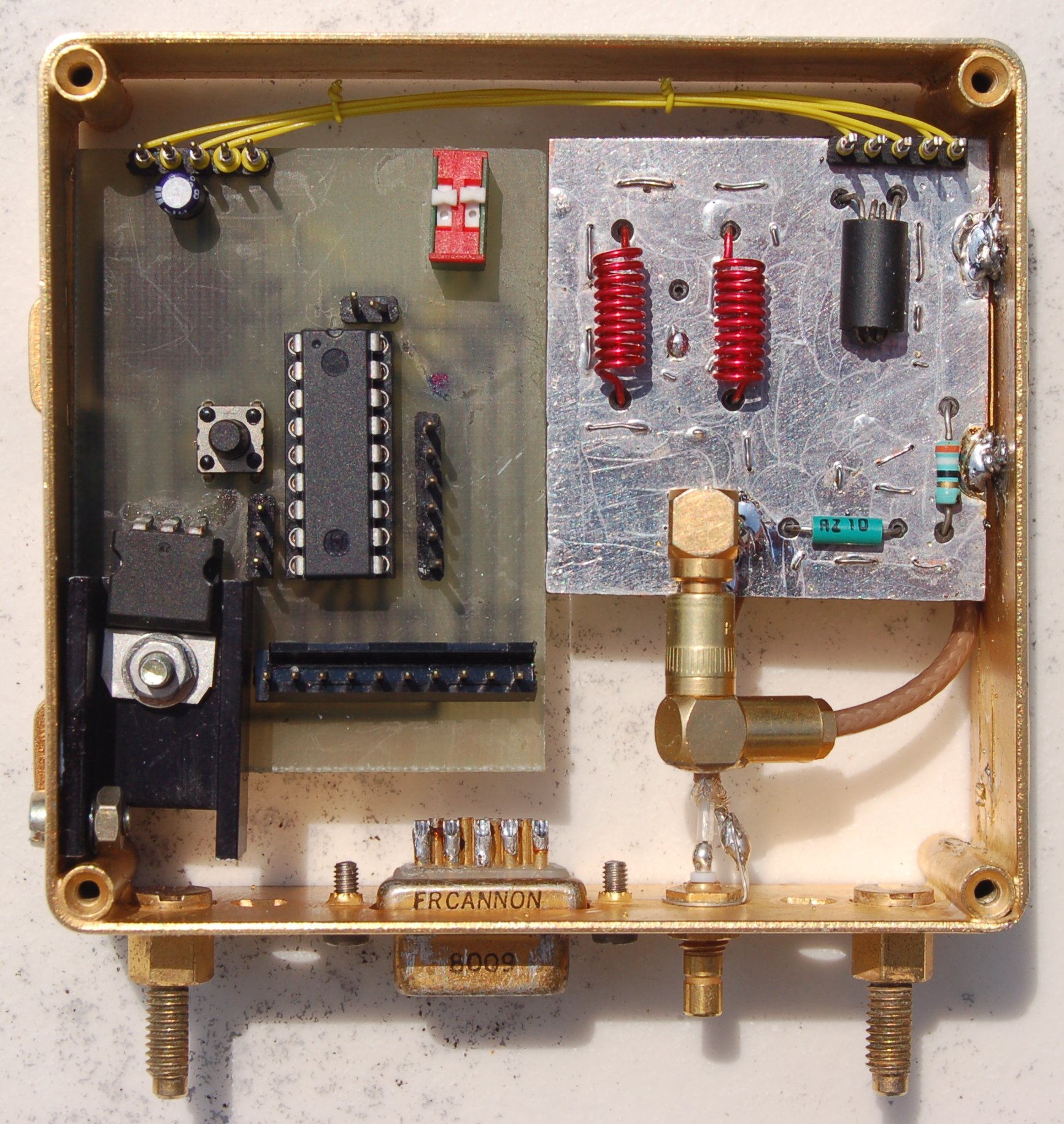
A SI-570 based frequency synthetizer for the Telerad LB740


Hardware

  • Schematic
  • Software

  • Pic16F628A binary
  • Details

    The TELERAD LB740 Model B VHF receiver lets the user selects four crystal frequencies with a provision for a remote configuration. This nice receiver has been designed to be 24/24 powered on for years. It only needs the crystal fitted for the required listening frequency.
    Having been given two working units, I decided to replace the crystal oscillator module by a more modern frequency synthetizer that lets me quickly configure the required frequency.

    After a few tests with a DS1085 oscillator - not enough stable for that usage - I rework my design around the wonderful SI-570 from Silicon Laboratories using the LVDS model. A few days later, a replacement module was running which offers four banks of four frequencies and a channel scan function.

    This new module plugs inside the original slot without any modification, excepted an optional wiring from the COMMA Card connector (pin 10) to the module DB9 unused pin 5. This is for the scanning function gets the squelch signal. Any change detected in the frequency selector will immediatly tune the synthetizer to the programmed frequency, the 'Remote position' been now used to select the scan function.

    Frequencies should be programmed in the PIC16F628A FLASH before any use according to the following memory mapping (firmware V0.5).
    The four banks are selected through RA6/RA7 that should be tied either to Vdd or Vss:
    - BANK 1 starts at offset 0,
    - BANK 2 starts at offset 32,
    - BANK 3 starts at offset 64,
    - BANK 4 starts at offset 96.

    Inside each bank:
    - FREQUENCY 1 configuration starts at offset 0,
    - FREQUENCY 2 configuration starts at offset 8,
    - FREQUENCY 3 configuration starts at offset 16,
    - FREQUENCY 4 configuration starts at offset 24.

    Each frequency configuration data is stored as:
    - BYTE 0:    Input Filter selection number,
    - BYTE 1-6SI-570 configuration word,
    - BYTE 7:    No scan on that frequency when not null.

    The following data should be computed before programming:
    - the oscillator frequency (Fosc) as:
    Fosc = Frec - 21.425 (Fosc & Frec in MHz)
    - the LB740 input filter selection number as:
    Set to 0 for Fosc <= 105.550MHz (Frec <= 126.975Mhz)
    Set to 1 for Fosc <= 114.550MHz (Frec <= 135.975Mhz)
    Set to 2 for Fosc <= 122.550MHz (Frec <= 143.975Mhz)
    - the SI-570 configuration word:
    The configuration word should be computed accordingly to the Silicon Laboratories method.
    This requires the power on frequency and the related default configuration word be known.
    The later information is sent on the PIC serial link.

    A few parameters are hard coded in the firmware, at least with firmware V0.5:
    - SI-570 I2C address set to 0x55,
    - Wait 3 seconds after last Squelch activity,
    - External PIC reset (MCLREN),
    - No watchdog (WDTDIS),
    - Serial link @9600 bauds, 8 bits, 1 stop, no parity.

    All devices are powered with a 3.3V supply power excepted for the ERA1 MMIC.
    So be careful of not using ICSP with a 5V supply or disconnect the SI-570 power line before connecting ICSP...

    This firmware has been tested with a SI-570 BBA000107G (LVDS model starting at 10Mhz and with a 0x55 I2C address).
    The schematic has been designed for the SI-570 LVDS model making use of
    - a 4:1 home made impedance adaptation transformer,
    - a 135MHz low pass LC filter, and
    - an ERA1 MMIC ouput amplifier that provides the required 10dBm output level.


    Pictures

    Telerad LB740 Original 4 fixed frequency module
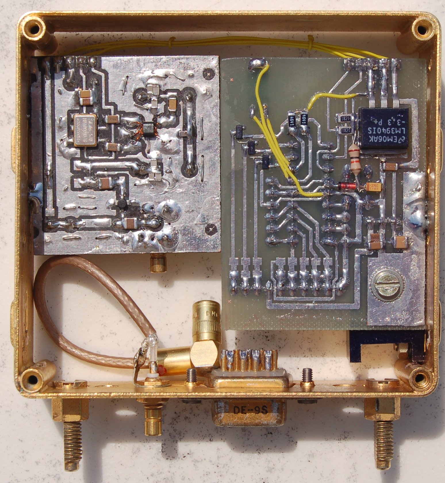
    SI-570 replacement prototype
    SI-570 detail