A simple ADS-B Decoder


I managed to make this ADS-B decoder development freely available for all but it costs me a lot of personal time and resources.
So if you like it and use it, please consider a donation. Even the smallest amount is welcome as it will help me acquire new tools and equipements.

Thanks David, Nigel, Alexandros for the donation, Guenter for the PCB and Bev (COAA) for the PP licence.


Hardware

Receiver front end:
Uses:
- SAT Tuner,
- SAW Filter,
- NE592,
- AD8307,
- LM311.

Decoder:
Uses:
- PIC18F2550,
- MAX232 and/or FT232R.

Software

PIC firmware:

Decodes and processes any TTL ADS-B / MODE-S signal.
Two modes of operation:
- Decodes and outputs raw data,
- Decodes, processes and outputs extended data.

Three send out options:
- Only 112bits frames or all frames,
- CRC validated frames for all DF frames, or all frames without any check,
- At 115200 Baud (Serial and USB) or 1M Baud (only through the FT232).

Windows Application:

A simple application that processes the extended data stream sent by the decoder. It:
- Configure the decode,
- Displays major information,
- Stores raw data in a log file called Output.txt.

External applications, such as Plane Plotter, would be able to process that log file.

Details

This project aims at creating a hobbyist ADS-B receiver with on the shelves components.
It uses a PIC18F2550 to decode ADS-B pulses received by a modified SAT tuner and demodulated by an Analog Device AD8307 log amplifier.

I tried to keep it as simple as possible and spit it in three parts.
- A home made receiver front end which converts the 1090MHz carrier pulse modulation signal to a low frequency logical signal,
- A µprocesseur decoder which decodes the logical signal and converts it to its hexadecimal representation, or more,
- A Windows program that will display the basic data send through the decoder serial output.

The decoder output format as been integrated in the well know Plane Plotter application enabling anybody having completed all or parts of that project to display the ADS-B / MODE-S collected data.

Receiver front end:

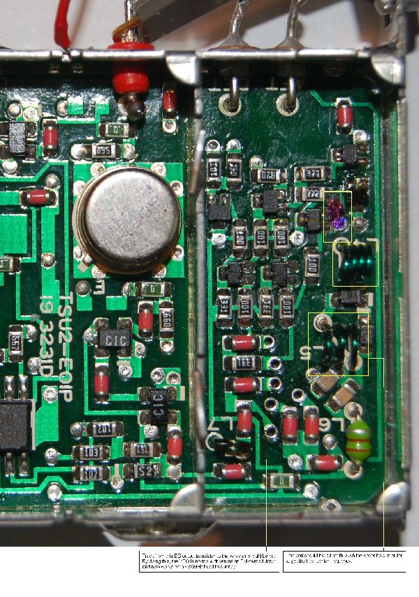
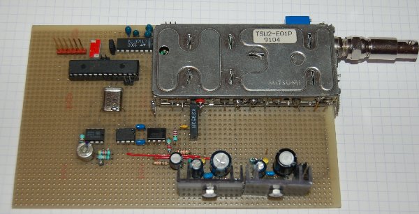
A Mitsumi SAT tuner was chosen as it could be easily modified to operate as a two IF sections receiver with a 38Mhz carrier ouput instead of the FM demodulated base band.

VFO modifications & IF ouput VFO modifications

However, any other design can be used if it provides either:
  • A low level carrier HF signal: the 70MHz output from an off the shelf SAT demodulator or from a professionnal receiver for example.
     In such a case, the NE592 inputs will be connected to that output.
  • A high level demodulated digital signal: the output of a another 1090MHZ front end demodulator such as the miniADSB frontend which is available as a kit here.
    In the later a case, the miniADSB frontend output - not TTL compatible - should be connected to the PicADSB decoder input though a analog to TTL converter.
    A comparator based converter such as the one used in my frontend will work nicely.


PIC Decoder:

As previously noted, the PicADSB decoder can be used with any other ADS-B receiver, or front-end, provided it delivers a 5V TTL level signal. Be aware that it has not been designed for a commercial and/or professional use.

Decoding
Latest firmware handles the following frames and data fields:
All DFs:AA (Aircraft address)
DF00:AC (Altitude)
DF04:AC (Altitude)
DF05:ID (Identity)
DF16:AC (Altitude)
DF17:ME (Messages 0-22,28)
DF18:ME (Messages 0,2,3) (partly in V2.x)
DF20:AC (Altitude)
DF21:ID (Identity)

Hardware options
Our design includes a lot of options of which:
  • 3.6V power supply:
    This is done by using two diodes to drop the 5V supply, and the input signal.
    One can discard these diodes as they will only be needed in further developments.
  • Alarm display:
    A short pulse is send on the RA4 output when an emergency SQUAWK is received.
    A NE555 like timer can be used to drive a LED for a greater period of time.
  • I2C control:
    A data sequence can be send to an external I2C device.
    This may be used to initialize an I2C frontend.
  • High speed output link:
    A MAX232 like converter is used to convert the TTL level PIC serial output with a bottleneck 115200 Baud maximum speed.
    A far better speed (tested upto 1M baud) can be achieved by using a serial to USB converter such as the FT232R.
    The USB 5V power supply could then be used to power the full decoder leading to as stand alone receiver.

Programming
The PIC18F2550 processor should be programmed with the very latest version of firmware which is provided as a ready to burn HEX file. As our current firmware do not provide a bootloader, programming should be done through the ICSP (In Circuit Serial Programming) interface. The related IO signals are not used by our design. We strongly recommend using the PicKit2 device.

Wiring
Feel free to adapt our design to your needs provided you keep the IO assignments we described on our schematics.
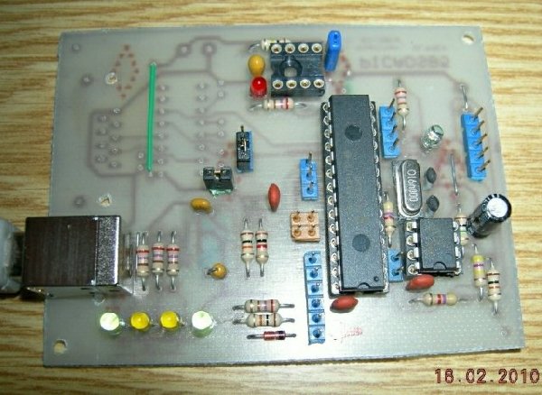
A PCB including everything needed to connect the MiniADSB frontend and the high speed output has been made available by a friend OM, DL4MEA.
More information could be found on his 'PCB for Rxcontrol PIC 18F2550 based ADS-B decoder' dedicated page. Feel free to contact him by mail here
.

From the processor side:
  • The demodulated TTL signal is applied to the RC0 digital input,
  • A signal level information (0-5V) can be supplied to the RA0 analog input,
  • Decoded output (0-5V) is available on the RC7 serial output,
  • Input commands (0-5V) are send to the RC6 serial input,
  • Switches connected to RB2 and RB4 enable real time selection of operation mode:
    • CRC: Frame integrity is verified when the RB2 input is true.
      when set, DF11/DF17 frames for which integrity was not verified aren't sent, all other DF frames are sent with the '*' prefix.
      when unset, all frames are send with the '*' prefix.
    • 112: 112 bits frames will be sent when the RB3 input is true
      when set, frames will be filtered to only ouput long (112bits) ones including DF17,
      when unset, all frames are sent whatever their length is.
    • SPD: Low speed link is selected when the RB4 input is true at reset
      when set, a 115200 baud speed is selected which could be used either with Serial or USB link option,
      when unset, a 1M Baud speed is selected which is to be only used with the USB link option.

Software Configuration
The PicADSB decoder allows for remote software configuration. This will be done by sendind one character commands through the serial or USB link.

The following commands are implemented by the latest firmware:

CTRL-S XOFF - Transmit OFF for frame data only, not for query responses
CTRL-Q XON  - Transmit ON

RSoftware reset
?Software version
oOptions status

SClear statistics
sDisplay statistics

CClear cache table
cDisplay cache table

PEnter Lat/Lon position values (2x8 hexadecimal characters)
pDisplay Lat/Lon position values

TEnter I2C sequence (V2.x only)
tDisplay I2C sequence (V2.x only)

EClear ICAO code
eEnter ICAO code (6 alphanum characters)
IDisplay ICAO code
iDisplay ICAO code

AClear Alarm on ICAO code
aSet Alarm on ICAO code
FClear filter on ICAO code
fSet filter in ICAO code

XClear extended mode
xSet extended mode

WAlways send raw
wNo raw data in extended mode with 112bits only frames option selected

LAlways send raw Lat/Lon position
lSend decoded Lat/Lon position

0Select PicADSB native output format
1Select PicADSB native output format with not verified CRC frames announced as good
2Select minimal raw data format with optional CRC verification
3Select AVR compatible raw data format without any other control
4Select Tagged Raw data format for MLAT without any other control


Nota:
- Monitored ICAO code and all options (alarm, filter & mode) are made persistent to reboot.
- A small delay should be inserted between each send data byte for commands 'P' and 'E'.
- When needed these options could be disabled by sending the 'W', 'l' and 'X' commands.

Output formats
Four output formats can now be selected through software commands '0', '3', '4', 'x' and 'X':

  • Basic AVR format ('3')
    Starting with firmware 2.6, an option had been added which can be used to select the same raw format as the one used by Edward Cardew in his AVR based receiver.
    Here PicADSB will only translate the received pulses in a numerical data sequence which is sent through the serial or USB link.
    That's the way the 'PlaneGadget Radar - ADS-B Receiver' and the Edward Cardew's AVR based receiver work.
    The Plane Plotter application will handle all the MODE-S/ADS-B decoding when configured for the 'AVR receiver'.

    The basic AVR format is selected by sending the '3' command..

    Frame starts with the * character prefix, followed by 14 (56 bits frames) or 28 bytes (112bits frames), a terminal ';' and ends with a CRLF sequence.
    *RAW;<CR><LF>

  • Tagged RAW format ('4')
    Starting with firmware 2.8, a time code can be added to the raw data frames.
    The Tagged RAW format is selected by sending the '4' command..

    Frame starts with the @ character prefix, followed by 26 (48bits tag + 56 bits frames) or 40 bytes (48 bits tag + 112bits frames), a terminal ';' and ends with a CRLF sequence.
    @TAGRAW;<CR><LF>

  • PicADSB Raw format ('X')
    This is the simpliest of the PicADSB format in which received frames are sent as it in hexadecimal notation.
    It uses minimal internal resources and will give the maximal throughput when CRC verification is disabled.
    This format differs from the AVR one as the character prefix (PFX) will depend on the CRC verification.
    Frames field decoding should then be done by an external application.

    The PicADSB Raw format is selected by the 'X' command (don't forget to disable the basic AVR format through the '0' command).

    Frame starts with a one character prefix (PFX), followed by 14 (56 bits frames) or 28 bytes (112bits frames), a terminal ';' and ends with a CRLF sequence.
    <PFX>RAW;<CR><LF>

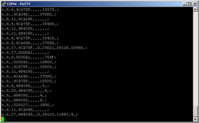
  • PicADSB Extended format ('x')   (click on the line below to see a sample)
    This the most evolved format in which many fields are send decoded. It is selected by default and requires the local position to be set.
    Due to computing power required, more frames could be dropped. The higher output speed, the higher decoded frames.
    The Plane Plotter application will handle those decoded data when configured for the 'RxControl receiver'.

    The PicADSB Extended format is selected by the 'x' command (don't forget to disable the basic AVR format through the '0' command).

    Frame starts with a one character prefix (PFX) and ends with a terminal ';' followed by the CRLF sequence. Fields are comma separated.

    <PFX>(RAW),LVL,TYP,ADR,CLS,CAT,CPR,LAT,LON,ALT,IDT,VRT,ESV,NSV,MAG,AIR;<CR><LF>

    with:
    RAWRaw Frame data, 14 or 28 hexadecimal bytes, optional ('w'/'W' commands)
    LVLReceiver signal level, 0 to 255, decimal value
    TYPFrame DF type, 0 to 31, decimal value
    ADRICAO aircraft identification, 6 hexadecimal characters, from all DF
    CLSCall sign or spaces, 8 characters, DF17[1-4]
    CATAircraft category, 1 character, DF17[1-4]
    CPRCPR flag, empty or 1 character
    LATLatitude , raw data or decoded ('l'/'L' commands), empty or decimal value, DF17[9-18], DF17[20-22]
    LONLongitude, raw data or decoded ('l'/'L' commands), empty or decimal value, DF17[9-18], DF17[20-22]
    ALTAltitude, in feet, empty, decimal value or letter '@' for landed, DF17[9-18], D17[20-22], DF0, DF4, DF16, DF20
    IDTIdentification, empty or 4096 Code, decimal value, from DF5, DF21
    VRTVertical rate, empty or signed decimal value, from DF17.19
    ESVEW velocity, empty or signed decimal value, minus=W, from DF17.19
    NSVNS velocity, empty or signed decimal value, minus=S, from DF17.19
    MAGMagnetic heading, empty or decimal value, from DF17.19
    AIRAir speed, empty or decimal value, from DF17.19

PFX is one of the following ASCII character
*Frame integrity cannot/was not verified
+Frame integrity was verified good
-Frame integrity was verified bad

The following other prefixes are used to flag replies to queries
|Reply to p position query
|LAT,LON<CR><LF>
<Alarm on ICAO monitor code
<ICAO<CR><LF>
!Alarm on '7500', '7600', '7700' or '7777' 4096 code (TYPE='S') or MODE-S (TYPE='M')
!ICAO,TYPE,CODE<CR><LF>
=Reply to ? identification query
|ADSB V.v (C)x.xxxxx<CR><LF>
^Reply to c print cache query
^Num,ICAO,4096,Trust,Count,Bail<CR><LF>
#Reply to s statistics query
#FrmErr,RecErr,CrcErr,LngFrm,DrpFrm,Time<CR><LF>
$Reply to o options list query
>Reply to i ICAO monitor code query

First Configuration
After programming, the PicADSB decoder starts with the following default configuration:
- Local position set to ORY (ORLY airport, France),
- Options 'Native format' (0), 'No raw data' (w), 'Extended mode' (x) and 'Position Decoding'(l) selected.

The first, and only thing to do, will be to configure the real local position.

A- Manual configuration
  1. Compute the required parameters as follow:
    - Get your latitude and multiplied it by 100000,
    - Change it to a negative value for a Southern hemisphere location,
    - Convert the result in hexadecimal using the windows calc application,
    - Do the same for the longitude, with a negative value for a Western position.
      Exemple:
        Location 2.12345W/48.12345N gives -212345 and +4812345 which convert to FFFCC287 and 00496E39 in hexadecimal.
        This will be entered as the sequence 'PFFFCC28700496E39'.
  2. Connect the receiver to your PC,
  3. Starts any terminal application that enabled using serial communication, such as HyperTerminal or Putty,
  4. Set it to the correct port, speed (115200 Baud or 1M Baud), data length (8), parity (none), handshake (none),
  5. Power up the receiver with the antenna disconnected,
  6. You should see a welcome message displayed,
  7. Send the 'CTRL-S' sequence to stop the data flow (Ctrl and S keys pressed together),
  8. Send the 'P' command ('P' key pressed),
  9. Enter position as 2x8 characters string made of the hexadecimal coded Latitude followed by the hexadecimal coded Longitude,
  10. Verify input by sending the 'p' command ('p' key pressed),
  11. Enable the data flow by sending the 'CTRL-Q' sequence,
  12. Connect the antenna, you should see the data flow.

B- Software configuration
  1. Download and starts the WinADSB application.
  2. Connect the receiver to your PC and power it up.
  3. Select the communication port and speed in the displayed configuration windows.
  4. Then enter your latitude and longitude coordinates the décimal (DD.MMMMM) format.
    North and East positions should be entered as positive values while South and West positions are entered as negative values.
  5. Click on the 'DONE' button, and voila, the application starts to display received information provided the selected communication port is the good one.


More details can be found here on my blog, in French I'm sorry.

Pictures

The receiver prototype
DL4MEA decoder PCB prototype
Signal sent to the PIC
Output on serial link (Extended Long)Output on serial link (Extended Short)
Test application (click for video) Gateway application (click for video)


Last revision: 06/26/2010